The benefits of BIM are discussed at almost all the conferences concerning the construction industry. Better quality project documentation is one of the most often referred assets of projects modelled in BIM. Unfortunately, it is not clear whether this benefit was realised in the projects or not. So, there raise following questions:
- How exactly was the declared better quality measured?
- What exactly is meant by the better quality documentation in practise?
- How can a contracting authority assess the quality of the project data processed by BIM models?
This article will try to answer all these questions and introduce the reader into the elementary principles of the quality measurability of the project information.
Current project documentation control
The project documentation represents the repository of the majority of project information. The quality of the project documentation is measurable by incidence of errors. As for standard project documentation it is very demanding to detect the errors. The reasons may be that many regulations define only the general rules (1) or just the intended purpose of the project documentation use (2,3). This is a legitimate attitude but requires qualified human and thus necessarily subjective interpretation.
In practise contracting authorities are often facing the project documentation carried out with the quality at the edge of law. The human checking of the project documentation is a time demanding process as there is no time for more careful checking of the delivered documentation. This makes the situation for the contracting authorities even more difficult.
BIM solution
BIM model is a more complex information repository than standard project documentation. When using BIM, the standard form of project documentation is just an automated export from the model – outlet. The model outlet is a pre-set view on the data included in the model and can represent:
- 2D drawings, axonometry
- Visualisation and animation
- Tables (sheets, records etc.)
- Calculations (lighting, daylight illuminance etc.)
- Harmonograms
- Schemes
- others
As BIM model represents a unique source of generating the required outlets (including those necessary for project documentation), some of common errors are suppressed completely – i.e. floor plan, cross-section and sectional view always meet (as well as quantity take-off).
Another big advantage is the automated generating of the data, so the human labour is eliminated when generating data from BIM model.
See the diagrams 1 and 2:

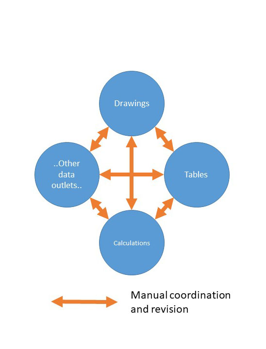
From this comparison the advantage of project data control by BIM is obvious. It is not necessary to go through all the project documents, it is possible to concentrate just on the contents and structure of BIM model. If the BIM model lacks any errors, then the model outlets are generated from the correct data.
It is possible to detect many errors in BIM just by the visual checking with the use of its viewing tool. Nevertheless, this type of control does not take the use of the potential of its digitalised content. Under certain conditions it is possible to control it by machine.
This is a completely new contribution of BIM that opens for contracting authorities.
Measurement of project information quality in BIM
To carry out the quality measurement of project documentation it is necessary to incorporate the whole process into to the construction projects framework.
Framework is described in the following diagram:
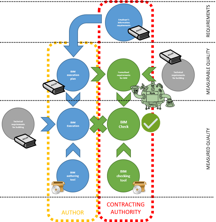
Diagram 3 – Framework of BIM quality measurement
At the first stage the contracting authority defines the requirements for data, it is so called EIR (Employer’s Information Requirement). The author carries out plan of BIM execution (BIM Execution Plan – BEP) before the contract is signed. BEP then launches (apart from other data and documentation) the execution of BIM model. BEP (together with other documents) becomes standard for BIM model of the project.
Requirements formalisation related to BEP represents a critical point of BIM check. Advanced example of the formalised requirements are those which define the requirements of technical regulations concerning the design, construction and building operation.
Formalised requirements are called parametric rules which aremachine readable and BIM has to meet them. Parametric rules can be applied automatically for model check with the use of SW tool.
Automated checks search whole BIM model and detect errors, i.e. parametric rules which were not met. In this case we can talk about objective, calculation-based quality measurement of project information.
Software tools specification
Automated checks allow fast and effective controls of the whole model which personnel would not be able to carry out. Automated check is conditioned by the use of software tools for BIM model check. There are various tools available in the market now.
Their common function is to search the model and check the space collisions of the model. More advanced tools use more complex checks, allow to tailor check sets and provide the interface for detected errors transfer to the author.
For the B needs it is necessary to choose such software tools which are fully compatible with the open format IFC (4).
Example of automated check of BIM model
In this part an example of model check with the use of Solibri Model Checker (SMC) tool (5), (6) is demonstrated. CTU uses SMC to check the models carried out in procurement contracts.
Checks flow
Parametric rules follow and condition one another. Thus the checks flow is given by pre-defined subsequence.
Let´s use the example of checking the size of the escape door. It is necessary to check first the following:
- model includes data objects such as rooms, walls and doors
- objects have geometric shapes, this geometry is sensible e.g.:
- a. minimal and maximal size, corresponding shape and location, e.g.:
- i. doors on one floor have the same threshold height,
- ii. …,
- b. no collision of the objects in room e.g.:
- i. wall in a wall
- ii. door opening is not in collision with other elements
- iii. …,
- a. minimal and maximal size, corresponding shape and location, e.g.:
- objects have corresponding interrelations among themselves and these relations are correct
- a. boundary relation – walls that have a relation to all the rooms they bound
- b. spatial relation – objects located on the same floor that identifies with the modelled reality,
- c. …
- .: objects have required properties e.g.
- a. Rooms are defined whether they are located in escape way or not
- b. Rooms have defined capacity
- c. ….,
- Logic checks such as
- a. all the designed rooms have an entry door,
- b. Escape way leads out of the building
- c. …
If all the above mentioned conditions are met, the software can define the direction and number of escaping people on the escape way. Based on parametrised control of fire safety regulations, the software can determine minimal size of the doors on escape way. Then these data are compared with the modelled door size on the escape way and detects those which do not meet the requirements – errors.
Areas/sets of model controls
All the parametric rules are organised in tree groups and subgroups according to the check target. Each group works independently and checks in each group are ordered in logical consequence – see the previous chapter.
The following table lists the main groups of checks and their description
| Group | Description |
| Architectural checks | Set of rules used to check the architectural model quality. These rules concern the validation of BIM model, space definition and relations of architectural model to the models from other areas (static, technical building equipment – TBE etc.) |
| BIM model coordination | Set of rules to check the relations among models from various professional areas (architecture, statics, TBE etc.) |
| validation – architectural-building part | Set of rules checking the quality of architectural model. This set involves subgroups of rules concerning the quality control and assurance. These checks should be carried out before further advanced model analysis, such as quantity take-offs, fire safety solutions etc. |
| model validation –Facility Management (FM) | Set of rules to check the use of space in the building |
| BIM model validation –technical building equipment | Set of rules to check TBE model quality. This set involves subgroups of rules concerning the quality control and assurance. These checks should be carried out before any further model analysis as the reliability and applicability of the results as well as the reliability of the data all depend on the quality model. |
| BIM model validation – building-construction part | This function checks static model quality. This function involves set of rules that concern the quality control and assurance. These checks should be carried out before any further model analysis as the reliability and applicability of the results as well as reliability of the data all depend on the quality model. |
| Energy analysis | Set of rules to check the model before it is used for energy analysis in applications and SW of third part. |
| Quantity take-offs | Set of rules to check the model before the quantity take-off calculation |
Each of the main group checks is further split in the tree system. Following diagram demonstrates the split of Architectural checks into the individual parametric rules.
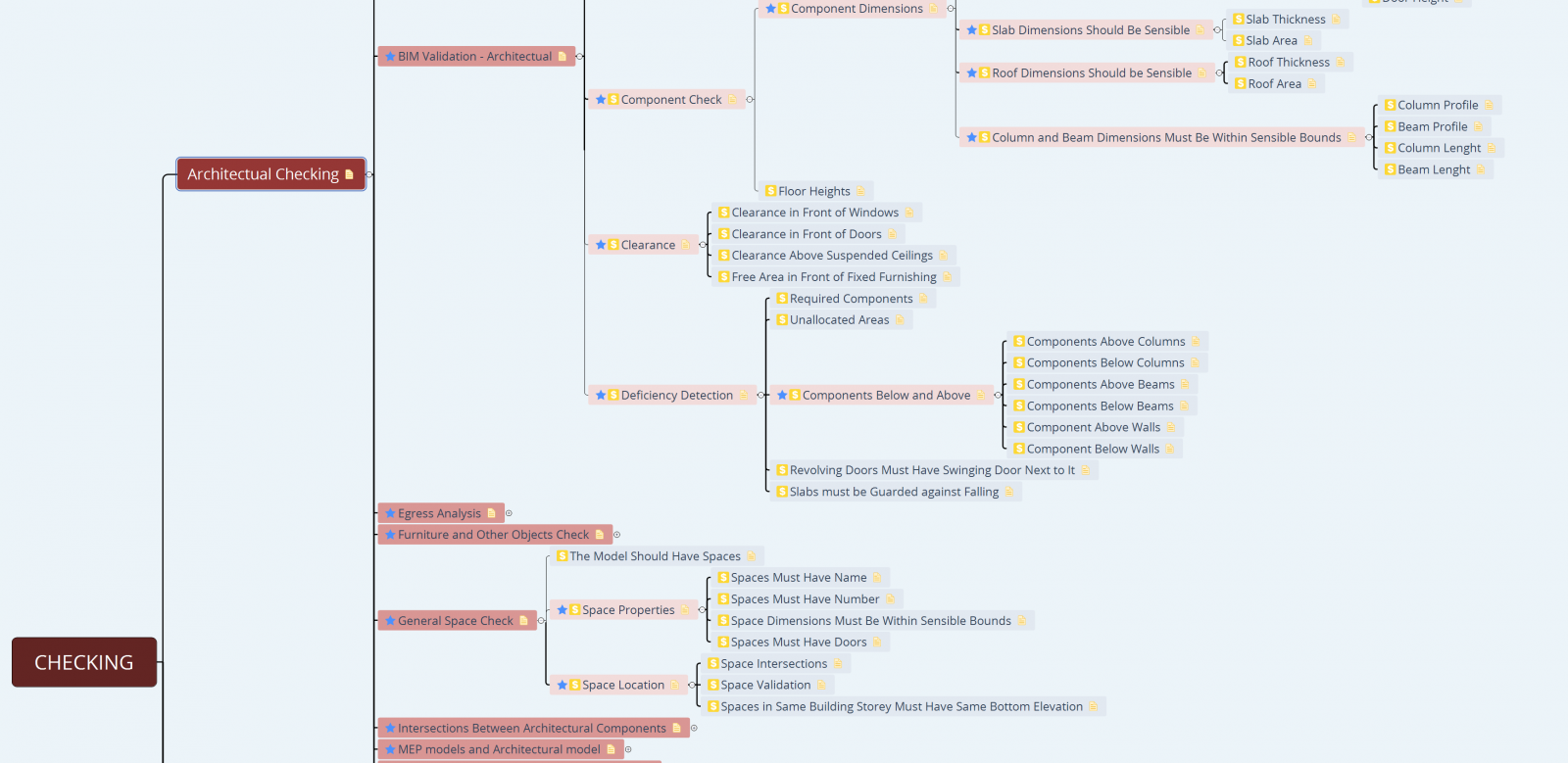
Diagram 4 – Control tree in SMC
Summary
Contracting authorities are usually coming with great expectations arising from the presentations at conferences. There are a few running projects using the BIM method financed by public resources. Construction offices often claim that their BIM models are quality and can be used in follow-up project stages. But there is a problem that lies either in inaccuracy or in different standards used by the various offices (if they use them at all).
On the other hand, a contracting authority does not have any tools, knowledge or labour capacity to check the quality of the delivered BIM model. Thus they often accept very poor models not possible to take use of. It is so called digital trash which issimilar to a situation when buying immobile vehicle based just on its producer´s presentation and assurance of its quality.
This way is the use of BIM by the contracting authority closed without any real contribution to them.
This article was to introduce BIM not only as an opportunity but also as responsibility. Responsibility for delivered models of certain quality which are applicable in the follow-up stages and project cycles.
As digitalisation is entering the construction industry, BIM model checks will become essential competence for each contracting authority as well as for construction work.
BIM model checks will be discussed in more detail in other articles.
References:
- https://www.zakonyprolidi.cz/cs/2009-268
- https://www.zakonyprolidi.cz/cs/2006-499
- https://www.zakonyprolidi.cz/cs/2016-134
- https://www.buildingsmart.org/compliance/software-certification/certified-software/
1 Comment